


Gary Shrader
Essay 30
AT&SF Class 5001
Lubricators
Gents,
Now that another wonderful O Scale West is receding into the rear view mirror, I am back to work on my two ATSF 5001 class 2-10-4's. There are 17 photos attached to this email showing how I added correct mechanical lubricators and working lubricator linkages to the models. In photo 1, I have pointed out the mechanical lubricators that came on the original USH model.
lubricators 1
⤵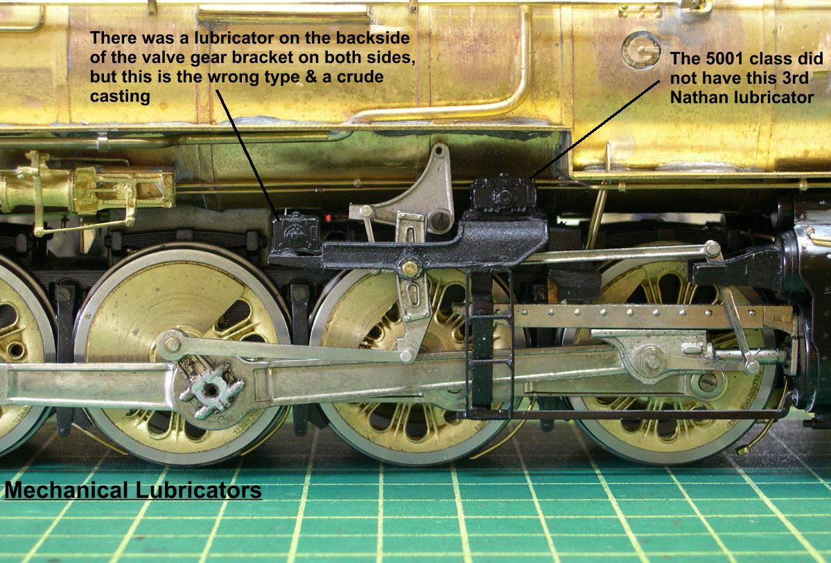
They are pretty crude castings and all 3 are actually incorrect for a 5001 (the USH model is a 5011, as you will recall). The 5001's did not have the 3rd lubricator located on the right side. The other two were not Nathan lubricators, but Chicago ones. A few years back, I made up a master for the Chicago mechanical lubricator and its vertical lever arm, as the ATSF used a lot of these lubricators. Dennis Mashburn cast them for me.
Some modifications are required on these Chicago castings for almost every application. I made them pretty flexible, so I only need one casting to serve on both sides of an engine. I made the two outer sides identical, so it does not matter which side needs the detailing. In photo 2, I have removed the entire valve gear bracket assembly from the frame to modify it for the new lubricators.
lubricators 2
⤵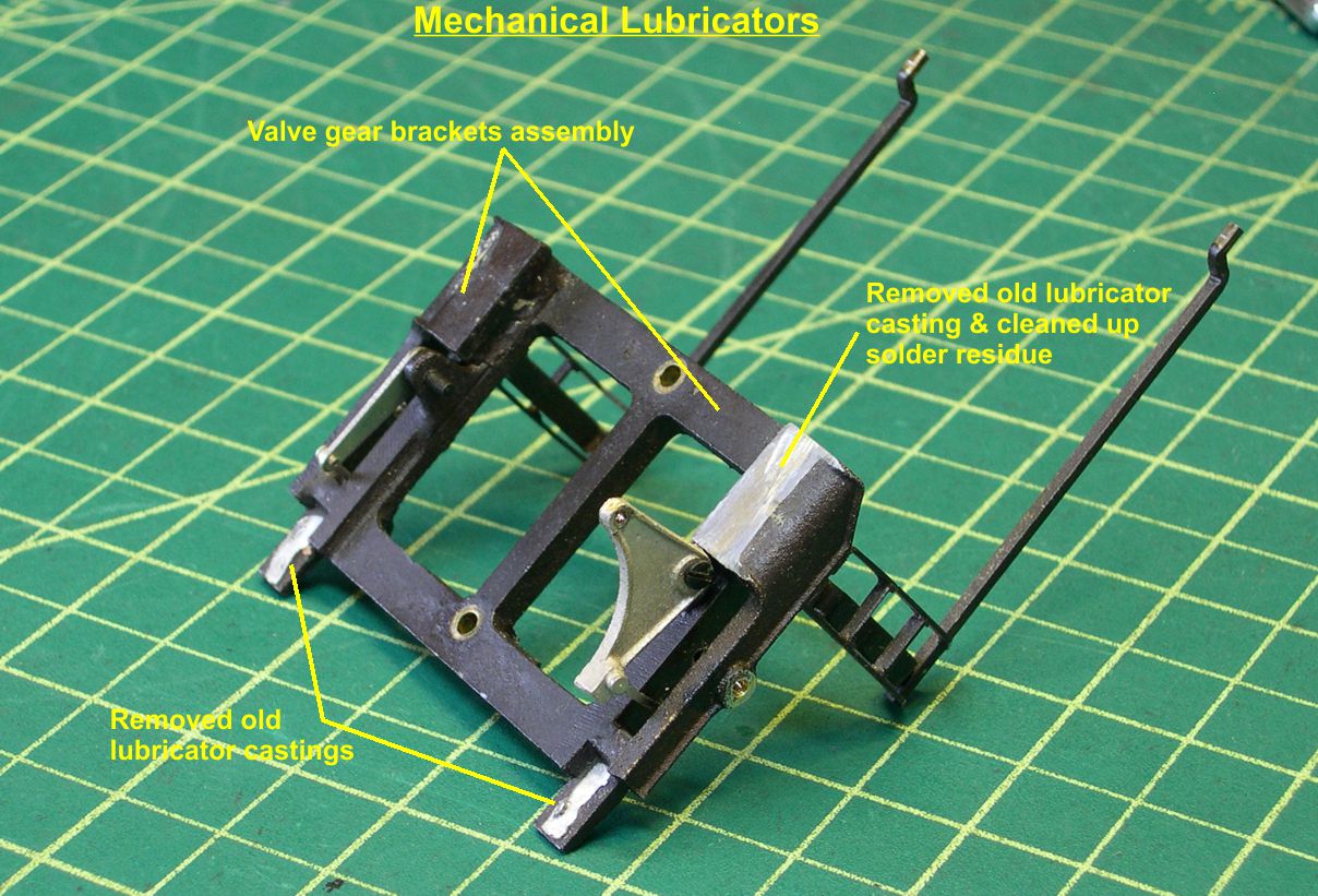
All three old castings were removed and the forward area that had the larger lubricator on a 5011 was cleaned up as shown. The platforms that the two smaller lubricators were mounted on are not usable for the new castings, so they have to be cut back. The Chicago lubricators were mounted to the end of the valve gear brackets in a vertical position instead of a horizontal one.
In photo 3, you can see how I cut back the valve gear bracket casting to the end of the valve gear bracket in preparation for mounting the new lubricators.
lubricators 3
⤵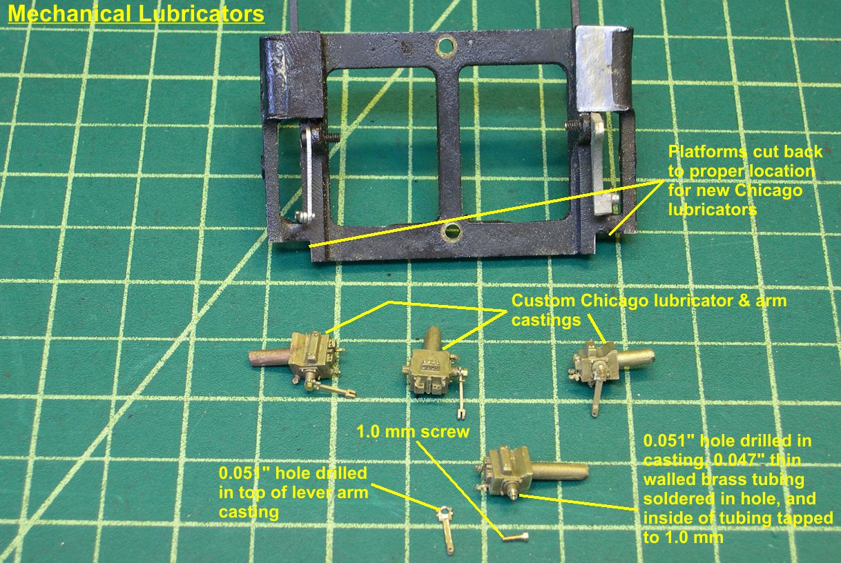
All 4 new lubricator castings are shown in photo 3 along with the vertical lever arms and some initial modifications to the castings. When I originally did the masters, I did not have a clear enough idea how I was going to do the mounting of the vertical lever arm. As a consequence, I have to make some modifications to accomplish that. What I have come up with works very well and is pretty easy to do. As noted toward the bottom of photo 3, I drilled a 0.051" hole into the lubricator casting and soldered a piece of 0.47" diameter thin walled brass tubing into it. This forms the "axle" for the vertical arm to pivot on. The tubing is from Special Shapes Co. The tubing is trimmed back to just a short stub sticking out of the casting. Then the inside of the tubing is tapped for a 1.0 mm hex head screw to hold the lever arm in place. The top 3 lubricators in photo 3 have the lever arm mounted, while the bottom one is in pieces to illustrate the construction. Of course, the top hole on the vertical lever arm casting has to be enlarged to 0.051" to rotate easily on the pivot. The small hole in the clevis will later be enlarged slightly to 0.018" to accommodate a 0.015" brass wire as the pivot on that end.
Next, as shown in photo 4, the detailing is filed off of one side on each casting, and the sprue is cut off and filed smooth.
lubricators 4
⤵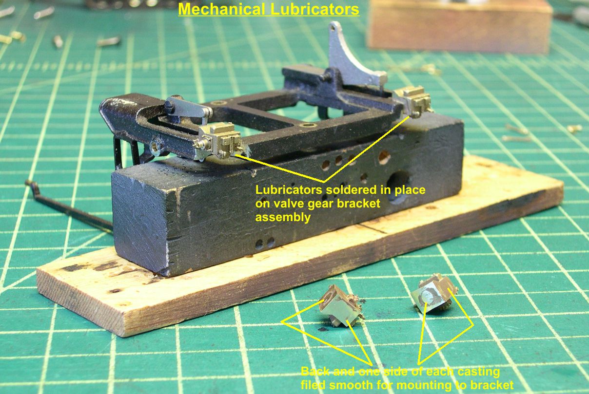
The castings are then soldered in place on the valve gear brackets. For many applications, it would not be necessary to file the detailing off the inside of the castings, but in this case it was easier than modifying the valve gear bracket casting.
When I made the masters for the Chicago lubricators, I put dimples in both the supply fittings on the bottom and in the support brackets on the back, so one can easily drill 0.016" holes for the oil lines as shown in photo 5.
lubricators 5
⤵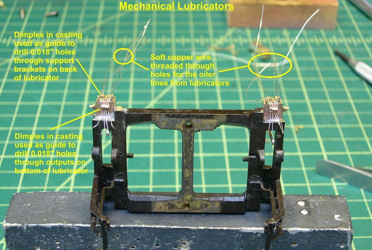
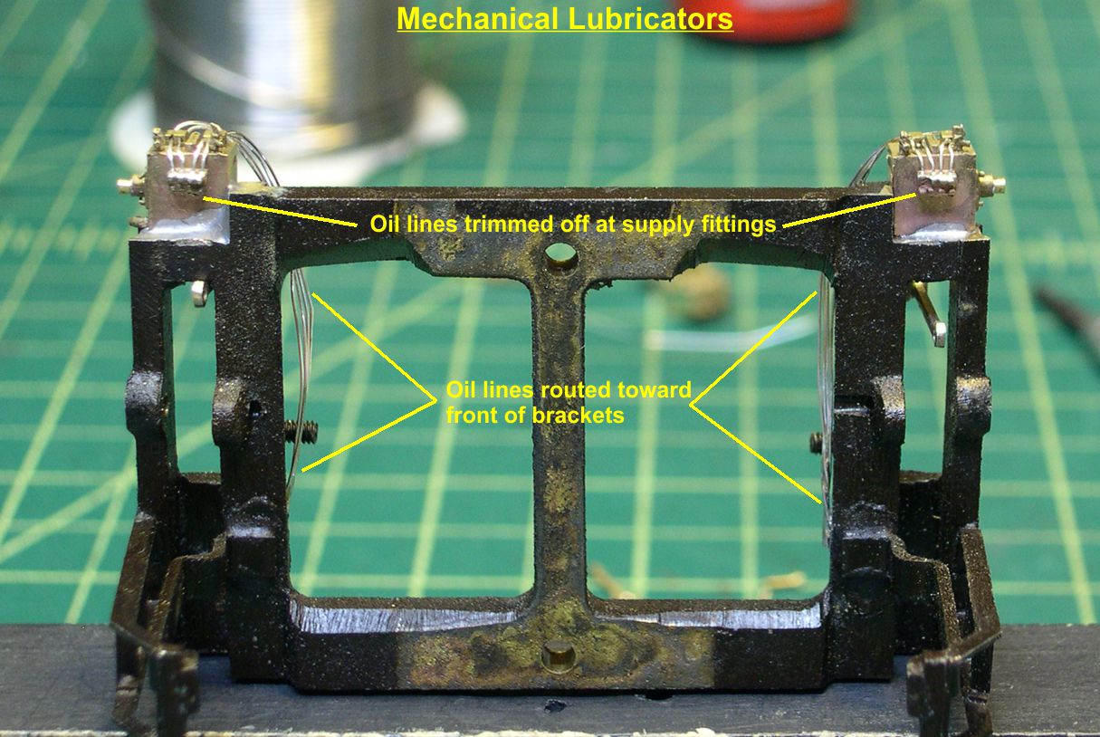
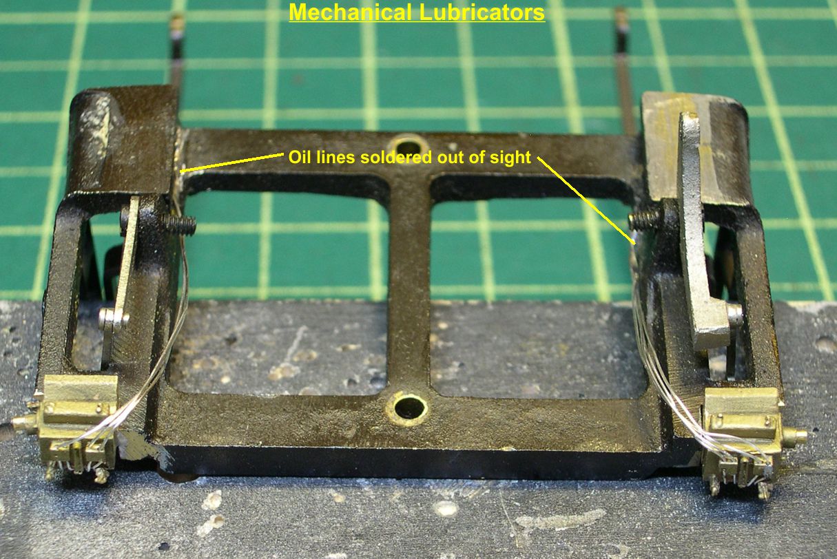
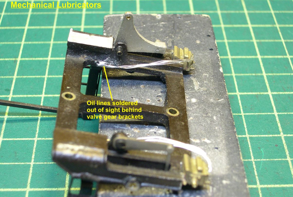
I then string soft copper wire taken from stranded wire into the holes to form the oil lines. The fact that the soft copper wire gets all bent up is actually an advantage, as that is exactly how the soft copper tubing of the prototype oil lines wound up most of the time. You don't really want them all nice and neat. I then soldered the wires into the supply fittings on the bottom and snipped them off flush on one side as shown in photo 6. It's not really necessary to solder the wires into the support brackets. The wires are then routed toward the front and hidden behind the valve gear brackets as shown in photos 6, 7, and 8.
lubricators 6
⤵
lubricators 7
⤵
lubricators 8
⤵
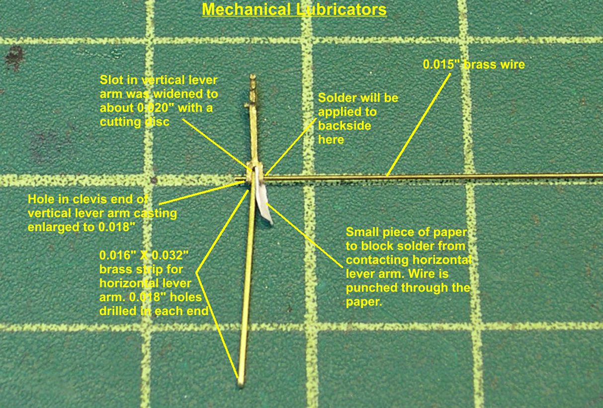
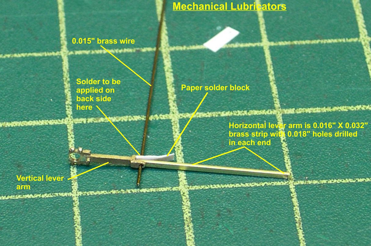
Making very small pivoting joints is not the easiest thing to do, as anyone who has tried will attest. However, I have developed a way to make it a lot easier. The biggest problem is soldering in a pivot rod without soldering the whole joint solid. I use a small piece of paper trapped in the joint to block the solder from going where I do not want it. In photos 9, 10, 11, and 12, you will see how this works.
lubricators 9
⤵
lubricators 10
⤵
lubricators 11
⤵
lubricators 12
⤵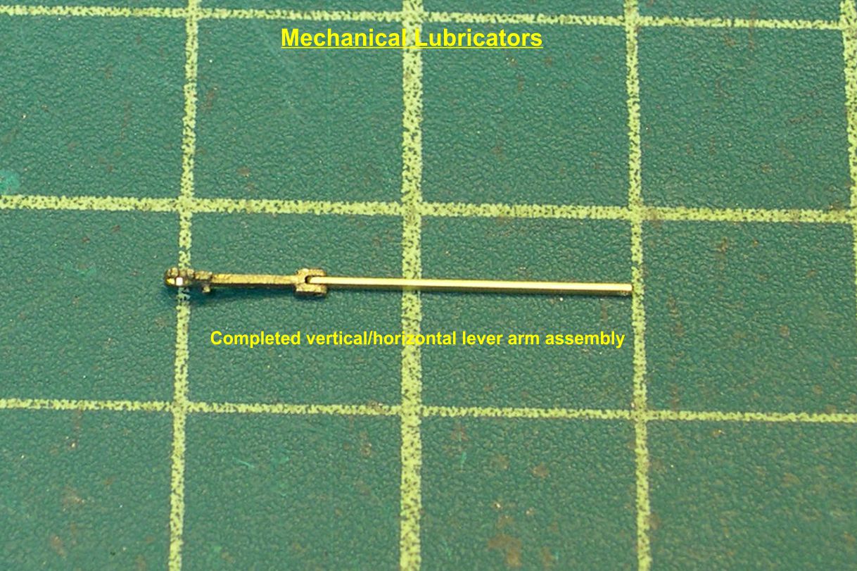
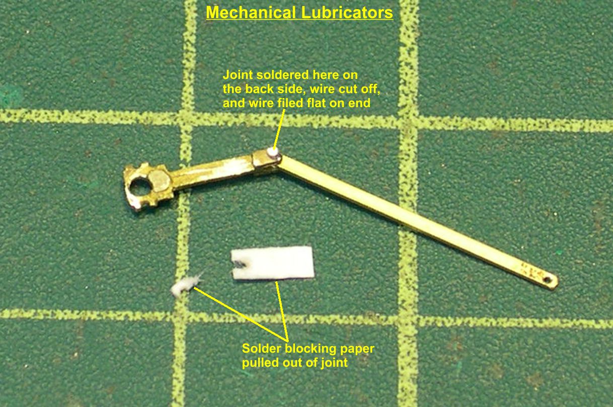
You pierce the paper with the pivot rod so the paper is tight against the rod on all sides. Then the soldering is done on the side next to the paper, and the paper blocks the solder from going on into the joint. After soldering, just pull the paper out of the joint, as in photo 11, and trim the ends of the rod back to the clevis on both sides. Now you have a nice freely moving joint. Keep in mind that the horizontal lever arm is only 0.016" X 0.032" strip brass, so that joint is pretty tiny. The finished arm assembly is shown in photo 12.
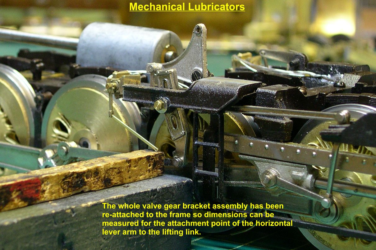
In photo 13, I have reassembled the valve gear bracket assembly to the frame in order to measure accurately how long the pivot point that attaches to the lifting link needs to be.
lubricators 13
⤵
The pivot point on the lifting link is fabricated by drilling a 0.033" hole in the proper spot in the lifting link. Then a piece of 0.032" thin walled tubing with a piece of 0.015" brass wire inside it is soldered into the hole from the back side. The back of the lifting link is then filed flat. I then used the paper trick again to form the tiny joint between the pivot on the lifting link and the horizontal lever arm. The lever arm is placed on the pivot first, then the paper is placed over it, and then the 0.5 mm hex nut is put on top the paper. The hex nut is soldered to the 0.015" wire while the paper blocks the solder. The wire is then clipped off at the hex nut and filed flush with the nut. Photo 14 shows how the components are arranged prior to soldering.
lubricators 14
⤵
Photos 15 and 16 are close up views of the finished operating linkage on the new Chicago mechanical lubricator.
lubricators 15
⤵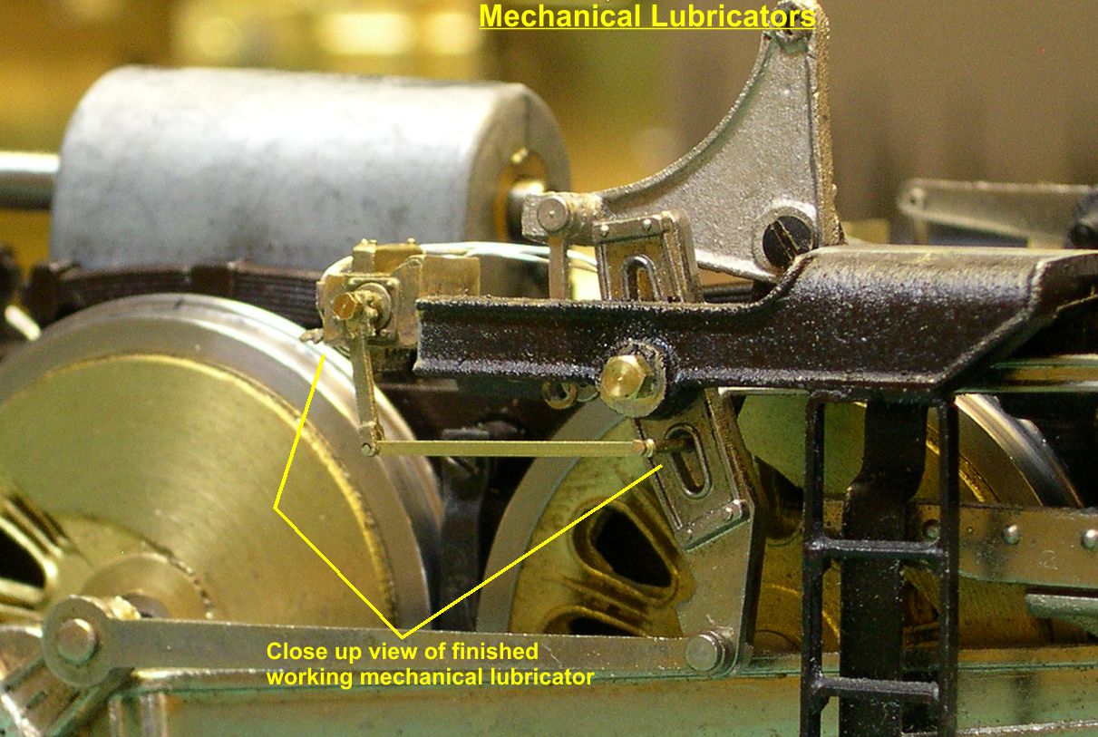
lubricators 16
⤵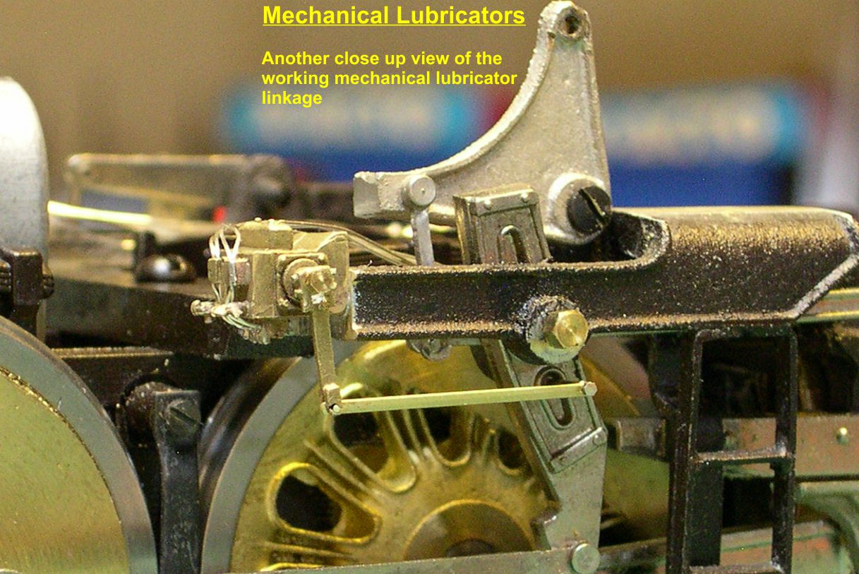
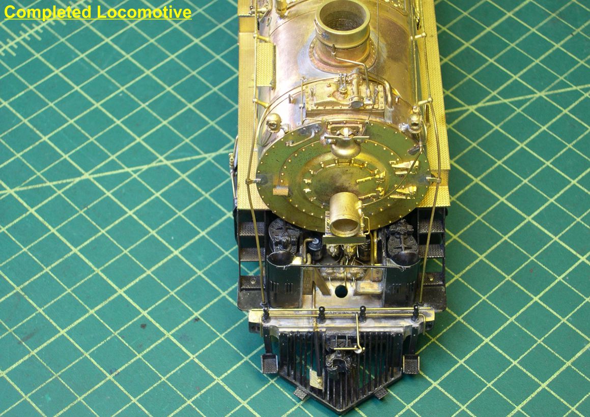
Photo 17 shows how the finished job looks on the assembled engine.
lubricators 17
⤵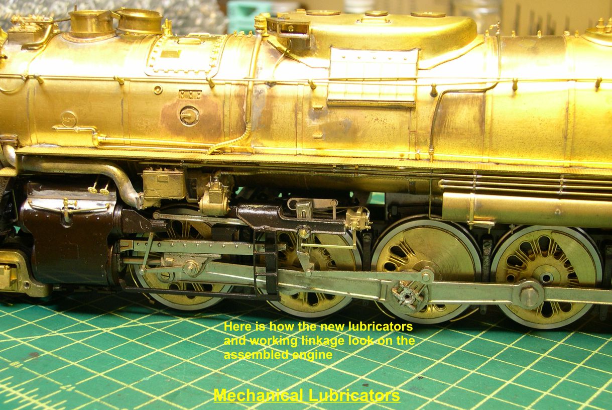
Quite a change in complexity, and they look really good operating as the engine runs on the layout.
Gary